(C / C++): Bitmanipulation mit bitweise Operatoren

Bitweises Komplement / Bitwise NOT

Der NOT-Operator (~) invertiert jedes einzelne Bit einer Zahl.

Beispiel mit 8-Bits:

 0000 0100 = 4
~0000 0100 = 1111 1011 = 251

Bitweises UND / Bitwise AND

Der AND-Operator (&) wird auf jedes einzelne Bit zwischen zwei Operanden angewendet. Das Ergebnisbit ist 1, wenn beide Bits den Wert 1 aufweisen.

Beispiel mit 4-Bits:

 0001
&1001
-----
 0001

Bitweises ODER / Bitwise OR

Der OR-Operator (|) wird auf jedes einzelne Bit zwischen zwei Operanden angewendet. Das Ergebnisbit ist 1, wenn eines der beiden Bits den Wert 1 aufweisen.

Beispiel mit 4-Bits:

 0001
|1001
-----
 1001

Bitweises exklusives ODER / Bitwise XOR

Der XOR-Operator (^) wird auf jedes einzelne Bit zwischen zwei Operanden angewendet. Das Ergebnisbit ist 1, wenn die beiden Bits unerschiedliche Werte haben.

Beispiel mit 4-Bits:

 0001
^1001
-----
 1000

Linksverschiebung / Left shift

Bei der bitweise Linksverschiebung (<<) werden alle Bits um die angegebene Position nach links verschoben.

Beispiel mit 4-Bits:

0001 << 1 = 0010
0001 << 2 = 0100

Rechtsverschiebung / Right shift

Bei der bitweise Rechtsverschiebung (>>) werden alle Bits um die angegebene Position nach rechts verschoben.

Beispiel mit 4-Bits:

0010 >> 1 = 0001
0100 >> 2 = 0001
1010 >> 1 = 0101 

Bit löschen

Will man in einem Byte mehrere Bits auf 0 setzen, wird dazu die UND-Verknüpfung verwendet.

PORTB &= ~(1 << 0)

Löscht Bit 0

Sollen gleichzeitig mehrere Bits gelöscht werden:

PORTB &= ~((1 << 0) | (1 << 2));

Löscht Bit 0 und 2 in PORTB

Bit invertieren


PORTB ^= (1 << 3);

Invertiere das dritte Bit

Bit setzen


PORTB |= (1 << 2);

Setzt das Bit 2 auf 1

Beispiel Methoden:


void set_PORTB_bit(int8_t  position, int8_t  value)
{
	// Sets or clears the bit in position 'position'
	// either high or low (1 or 0) to match 'value'.
	// Leaves all other bits in PORTB unchanged.
	
	if (value == 0)
	{
                // Set bit # 'position' low
		PORTB &= ~(1 << position);
	}
	else
	{
                // Set bit # 'position' high
		PORTB |= (1 << position);
	}
}

void set_Pin_Mode(int8_t  position, int8_t  value){
	if (value == 0)
	{
                // Set bit # 'position' to input
		DDRB  &= ~(_BV(position));
	}
	else
	{
                // Set bit # 'position' to output
		DDRB  |= (1 << position);
	}
}

Nützliche Links

mikrocontroller.net: Bitmanipulation

wikipedia: Bitweiser Operator

stackoverflow.com: How do you set, clear and toggle a single bit?

LearnCpp.Com: Bitwise operators

Logic Gate Simulator

AVR: Unterschied zwischen sleep_cpu() und sleep_mode()

Die zwei Methoden unterscheiden sich nur beim Handling des SE-Bit. Bei der Methode sleep_cpu() muss durch den Code sichergestellt werden, dass zuvor das SE-Bit gesetzt wird und nach dem Aufwachen der CPU das SE-Bit wieder gelöscht wird.

Beispiel mit sleep_cpu():


    sleep_enable();
    sleep_cpu();
    sleep_disable();

Beispiel mit sleep_mode():


    sleep_mode();

Nützliche Links

avr-libc: sleep

AVR: ATtiny13 / ATtiny25 / ATtiny45 / ATtiny85 Sammelsurium

Übersicht

Microcontroller with xKB of programable memory:
Attiny13 = Microcontroller with 1KB
Attiny25 = Micocontroller with 2KB
Attiny45 = Microcontroller with 4KB
Attiny85 = Microcontroller with 8KB

CPU-Geschwindigkeit:
Attiny13/13A: default: 1,2Mhz (Fuse bit set: CKDIV8)
Attiny25/45/85: default: 1Mhz (Fuse bit set: CKDIV8)
max: 20MHz

Anzahl der Pins: 8Pin(s)
Anzahl der Ein-/Ausgänge: 6I/O(s)
Embedded-Schnittstelle: I2C, SPI

Attiny13/25/45/85:
Versorgungsspannung, min.: 2.7V
Versorgungsspannung, max.: 5.5V

Attiny13A:
Versorgungsspannung, min.: 1.8V
Versorgungsspannung, max.: 5.5V

DC Current per I/O Pin: 40.0 mA
DC Current VCC and GND Pins: 200.0 mA

Pinout

ATtiny Pinout

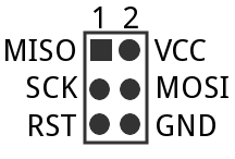
ISP Programming

2x3-pin ISP headers
2×3-pin ISP headers

ISP Pins

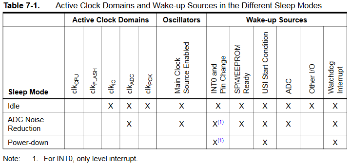
Sleep Modes

Sleep-Modes


/*
 * The 5 different modes are:
 *     SLEEP_MODE_IDLE         -the least power savings
 *     SLEEP_MODE_ADC
 *     SLEEP_MODE_PWR_SAVE
 *     SLEEP_MODE_STANDBY
 *     SLEEP_MODE_PWR_DOWN     -the most power savings
 */ 
set_sleep_mode(SLEEP_MODE_IDLE);

sleep_enable(); // enables the sleep bit in the mcucr register

sleep_cpu();      // here the device is actually put to sleep
	
// -------------------------------------------------
// THE PROGRAM CONTINUES FROM HERE AFTER WAKING UP
// -------------------------------------------------
	
sleep_disable();	// disable sleep...

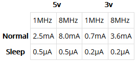
Power consumption

power consumption

Der Stromverbrauch wurde gemessen mit:

  • set_sleep_mode(SLEEP_MODE_PWR_DOWN);
  • ADC deaktiviert

Siehe folgender Artikel: technoblogy.com: ATtiny Low Power

Disable Analog to Digital Converter ADC:


ADCSRA &= ~(1 << ADEN);

Disable ADC Makro:


#define adc_disable() (ADCSRA &= ~(1 << ADEN)) // disable ADC

Arduino Methode:


power_adc_disable();

Interrupt


ISR(PCINT0_vect) {     // pin change interrupt
}
ISR(INT0_vect) {       // external interrupt
}
  • ISR needed for sleep to not reset program after interrupt
  • Every PCINTx will rise PCINT0_vect
  • Typically global variables are used to pass data between an ISR and the main program. To make sure variables shared between an ISR and the main program are updated correctly, declare them as volatile.

GIMSK |= (1 << INT0);          // Enable external Interrupt

MCUCR &= (0 << ISC01);	       // The low level of INT0
MCUCR &= (0 << ISC00);         // generates an interrupt request

Interrupt 0 sense control


sei();          // enable interrupts
cli();          // disable interrupts

Arduino Methode:


interrupts ();// enable interrupts
noInterrupts(); // disable interrupts

Libraries
315Mhz and 433Mhz Manchester encoding RF library which works on Arduino and ATTiny

Nützliche Links
Atmel: ATtiny Datasheet pdf
The pinouts of the most popular AVR processors
mikrocontroller.net: AVR-Tutorial: Interrupts
gammon.com.au: Interrupts
ATtiny: Fuse Restore using HVSP
mikrocontroller.net: Sleep-Mode